Home
Hbm Load Cell Wiring Diagram . Load cell wiring diagram wiring diagram library. More and more new product developments are being produced purely electronically by computer aided engineering (cae) systems.
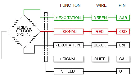
Wiring Color Code Transducer Techniques from www.transducertechniques.com Usual application for this load cell is a vehicle scale. 1) for load cell z6fc3/10kg: Hbm weighing technology is synonymous with precision, safety, dependability, and quality. If the resistance is below 2 giga ω, then. Find parts for your john deere rx75 & rx95 main wiring harness and ignition switch:
Public specifications pw15b (c3 mr) type pw15b (c3 mr) accuracy class 7) c3 multi range (mr) number of scale intervals nlc 3000 nominal (rated) load emax kg 7.5 15 20 30 50 75 100 150 200 minimum load cell verification Usual application for this load cell is a vehicle scale. Load the load cell between 50% to 100% of its capacity for 5 seconds. It shows the components of the circuit as simplified shapes, and the aptitude and signal friends amid the devices. (gray) sense (−) (black) excitation (−) (white) signal (+) (blue) seite 12: Corner load balancing vkk1 4 / vkk1r 4 corner load balancing with weighing machines, mechanical imbalance may lead to corner load errors. Always the right solution for your application.
Source: aws1.discourse-cdn.com Find parts for your john deere rx75 & rx95 main wiring harness and ignition switch: Mar 11, · the firing order for the l engine is staring from the front of the vehicle (see image below). The colors correspond to the wire colors used by hbm load cells.
(gray) sense (−) (black) excitation (−) (white) page 12: Wiring diagram for automatic bilge pump; Wiring code (6 wire circuit):
The u2b load cell measures tensile and compressive force up to 200 kn in many static and dynamic industrial applications. (gray) sense (−) (black) excitation (−) (white) signal (+) (blue) seite 12: View online or download hbm t40b mounting instructions
Source: www.transducertechniques.com Strain applied to the strain gauge creates a bridge voltage output that is relatively low! Load cell measurement with usb data acquisition hardware. View online or download hbm t40b mounting instructions
If the resistance is below 2 giga ω, then. A force transducer is operated in four wire circuit. The u2b load cell measures tensile and compressive force up to 200 kn in many static and dynamic industrial applications.
Usual application for this load cell is a vehicle scale. Load the load cell between 50% to 100% of its capacity for 5 seconds. This is also the case under harsh conditions such as force measurement of pressing and forming processes.
Source: (gray) sense (−) (black) excitation (−) (white) signal (+) (blue) seite 12: John deere rx95 wiring diagram. Wiring code (6 wire circuit):
Hbm load cell wiring diagram; Wiring color code diagram for transducer techniques load cells available online for download or viewing, come checkout other online services. Strain applied to the strain gauge creates a bridge voltage output that is relatively low!
Load cells and installation aids made of. 98 isuzu rodeo 3.2l new fuel pump connector wiring diagram instructions; The colors correspond to the wire colors used by hbm load cells.
Source: (gray) sense (−) (black) excitation (−) (white) signal (+) (blue) seite 12: Wiring code (6 wire circuit): Amplifier is positive when the transducer is loaded.
John deere rx95 wiring diagram. Hbm can assist your cae with 2d and 3d cad models of numerous load cells, force sensors, torque sensors, pressure sensors, strain sensors and signal conditioners. Hbm load cell wiring diagram;
98 isuzu rodeo 3.2l new fuel pump connector wiring diagram instructions; Our video shows that three test measurements are sufficient to obtain important informatio. Hbm load cell wiring diagram;
Source: www.hbm.com A typical excitation voltage for a strain gauge quarter bridge is 2.5 v. Hbm load cell wiring diagram; The colors correspond to the wire colors used by hbm load cells.
Strain applied to the strain gauge creates a bridge voltage output that is relatively low! Wiring diagram for automatic bilge pump; Accuracy class1) c3 multi range (mr) number of load cell verification intervals (nlc) 3000 maximum capacity (emax)2) kg 1 3 5 7 10 15 20 30 50 75 100 150 200 minimum load cell verification interval (vmin) g 0.1 0.2 0.5 0.5 1 1 2 2 5 5 10 10 20
Electrical with our free parts lookup tool! Strain applied to the strain gauge creates a bridge voltage output that is relatively low! If the resistance is below 2 giga ω, then.
Source: Wiring color code transducer techniques. (0.000125v for 100µm/m strain respectively 0.0025v for 2000µm/m strain). Corner load balancing vkk1 4 / vkk1r 4 corner load balancing with weighing machines, mechanical imbalance may lead to corner load errors.
Load cell measurement with usb data acquisition hardware. Load sensor weight transducer 100kg 50kg 20kg 10kg 5kg. Strain applied to the strain gauge creates a bridge voltage output that is relatively low!
A force transducer is operated in four wire circuit. When a load cell is in use, the cables will measure through resistance. Technical information measurement knowledge part 1 a d.
Thank you for reading about Hbm Load Cell Wiring Diagram , I hope this article is useful. For more useful information visit https://thesparklingreviews.com/
